DIY EV 8: Motor spin
Getting from our last checkpoint - pedal connected, ignition sequence working - to spinning the motor is quite simple. You basically connect 6 wires and press the pedal. But a lot of technical debt caught up with me so it took me almost a month to hit this milestone. I will cover these issues here because I think it’s important to be honest about the ‘one step forward, two steps back’ nature of a DIY electronics project, and then I’ll have a short section at the end where I show you the motor spinning.
I had no intention of dealing with my tech debt. My plan was to just get everything working on the bench, pack it all up, and do everything properly when I actually install it. This whole exercise is to prove to myself that I won’t end up over in my head when I pull my engine out of my car.
So, my working rule is, I need to get the motor spinning before I spend any more money. If I get the motor spinning, then I can probably deal with the rest of the issues, so I can proceed with buying cells and building a battery pack.
Flaky harness
The first issue that I had to deal with was that the wire harness from the Zombie, which I inherited from the seller, had flaky connections. This meant that some wires made no contact at all, and others would work some of the time but not all of the time. So I had to order a new harness from AliExpress. While waiting for that, I made a plan with crocodile clips connected directly to the board.
No CANBUS Comms
I am using a Mitsubishi Outlander PHEV Rear Drive Unit as my traction motor. You can read up on the motor here. They are cheap and plentiful in the EU. I do not live in the EU, but the easiest place for me to ship components from is the EU. If I was to do this again, I would buy a Nissan Leaf in Japan, ship it to Botswana, drive it over the border and strip it. They are also supported by the ZombieVerter.
Initially I just wired the inverter up and tried to get some sort of communication between the inverter and the ZombieVerter. Nothing happened. After a bit of investigating with a multimeter, I verified that 12v power and 350v power was getting to the inverter, but no CAN comms.
Iniitally, I thought it could be dodgy 12v wiring that was causing brown outs and messing with the electronics. The inverter 12v power was feeding directly from a ZombieVerter pin, which is risky, because if it pulls too much power I could fry the Zombie. So, I set up a relay that feeds 12v to the high voltage components when the inverter 12v pin on the inverter comes up. Note that, like the contactors, the inverter pin pulls to ground.
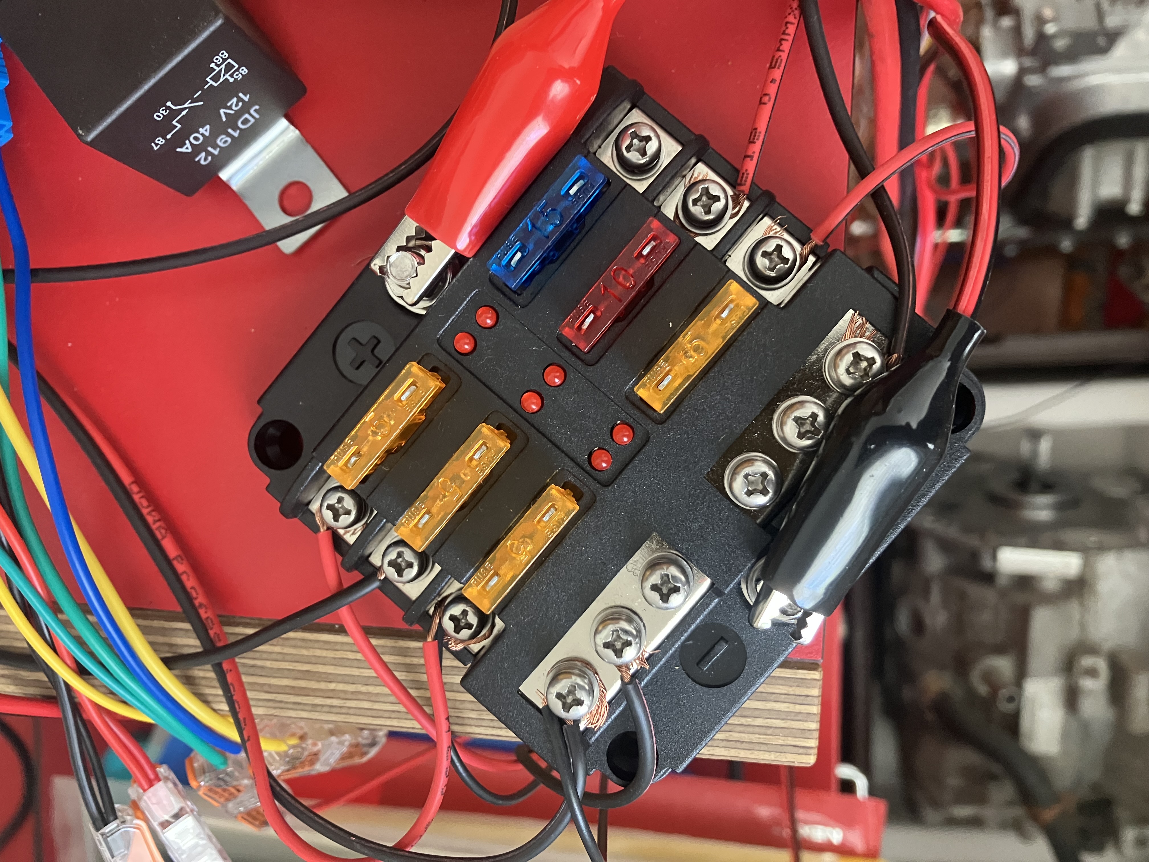
I also set up a fuse box to route clean 12v power from my 12 supply to all the components so that there weren’t any voltage drops to worry about.
Lost webUI
With all of the 12v wiring sorted, I fired it all up and… still no CANBUS comms. So, I thought, maybe this is a software issue. I had been having a lot of trouble with communicating with my Zombie. The web interface was flaky, the connection between the wifi chip and the controller board was flaky, upgrading seemed to make things more flaky.
While trying to find the optimal combination of web interface software version and Zombie controller software version, the wifi chip died. I was now completely unable to interact with the Zombie or set parameters, but the precharge sequence still worked, so presumably the Zombie was still functional.
So I went off and bought a new CANBUS based web interface chip from the openinverter store and waited for it to arrive. When it arrived a week later, I connected it up, and I got into the new web interface, but, because the CAN network wasn’t working, I couldn’t communicate with the Zombie. Try as I might, I could not get CAN comms, even though the IVT shunt was communicating over CAN fine.
A couple of openinverter forum posts later, the general consensus was that I needed to reflash the board and the old chip, so I bought an STLink V2 clone and a USB to UART cable, connected them up, and followed the instructions to manually reflash everything with new software. That took a couple of days, but, when I powered it all up, I finally got back my WiFi chip web interface and access to the Zombie.
I took another day to reconnect all the wires and set up the parameters so that precharge was working again, and then I turned back to the original problem. So I was now able to interact with the Zombie without being dependent on the CAN network.
Still no CANBUS comms
By process of elimination I had come to the conclusion that there was something about the CAN network physical setup that was broken. I removed everything except the IVT shunt and the Zombie, and it worked fine. As soon as I added another device, it all fell apart.
I started with the basics - is the network correctly configured when just two devices are connected?
CAN networks need to have two 120 ohm terminating resistors on either end of the network, which means that, powered down, the resistance between the CANH and CANL wires should be 120/2 = 60 ohm. When I checked with my multimeter, I got… 120 ohm. This meant that I only had one resistor.
I checked the Shunt - 120 ohm, as advertised. I checked the Zombie - nope. The Zombie is supposed to have a resistor. It is literally printed on the PCB. My only answer to this is that maybe the previous owner removed the resistor.
Anyway, I added a 120 ohm resistor, and, hey presto! The CAN network behaved as expected.
So, I spent about a month on various wild goose chases, the end result of which is that I have:
- A nice new wiring loom
- Proper 12v fusing and routing
- A relay to control the high voltage component 12v lines
- Completely up to date ZombieVerter and web interface software
- Knowledge of how to flash STM32 and ESP8266 chips via wired adapters
- All the bits in place to spin a motor!
Spinning the motor.
In the end, as I said in the beginning, the final step is quite simple. I connected up the high voltage lines, 12v input, and CANBUS cables to the inverter. Connected the 3 phase AC lines from the inverter to the motor and plugged in the the control harness. Fired everything up and completed the precharge sequence. Pressed the pedal and… the motor spun! Happy days. So many hours to get to this point, it feels like a real achievement, and I have learned a whole bunch.

Now I will tear it all down, store it in my garage, and start on building a battery. That involves learning about how BMSes work, connecting the BMS to the battery, wiring up a charger, and seeing if I can actually charge the battery by plugging it into the wall.