DIY EV 7: Ignition and pedal
Today we wire up our ignition switches and pedal.
The ignition switches serve the role of turning the car on and getting it ready to drive. The pedal provides a way for the driver to control the motor.
Ignition
When you turn a key in the ignition of a car, you may have noticed that there are several distinct stages. There’s the part where you turn the key, and the lights and radio come on, but your engine doesn’t crank. The key can sit in that position all day. Then there is the next part, where you turn the key further and the engine cranks and everything ‘really’ comes on.
The first step is called turning on the ignition. It turns all the control systems on. Ignition is a permanent state - current is continuously supplied to all the control systems. That’s why your key ‘rests’ in that position, and why you ’turn off’ the car by turning the key away from that position. What you are doing with that action is you are turning the control systems off.
The second part is called start. It actually gets the car running. Start is a momentary state. It is a signal, transmitted to the live control systems, telling them that the operator wants to actually drive now. That’s why the key doesn’t stay in that position - you just send the signal and then go back to the ignition state. If you hold the key in the start state in a petrol car, it will keep trying to start the engine by turning the starter motor, which may damage the vehicle.
Ok, how to these states and actions translate to an electric vehicle? Well, ignition is pretty much the same. We want to turn all our control systems on. The start signal basically gets the high voltage system up and running. Practically speaking, this means that when we turn on ignition the 12V power circuit goes live and everything boots up. When we turn to ‘start’, the automated precharge circuit procedure begins, and it ends when the main positive and negative contactors are closed and the high voltage circuit is fully live.
You can use a regular ignition barrel for this - and I probably will when I transplant all of this into my car - but for now, I am going to use a latching switch for ignition, and a momentary switch for start. In plain language, a switch that you turn on and off, and a switch that is only on when you are pressing it in.
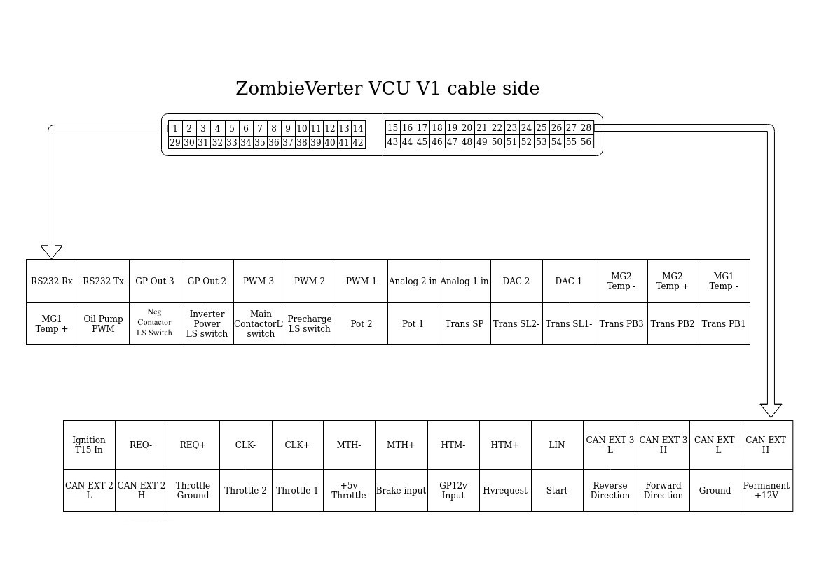
With the ZombieVerter this is all pretty simple. You use the latching switch to make the connection from your permanent 12V positive line to pin 15, and you use the momentary switch to connect the 12V positive line to pin 5.
My only issue, really, was that the ignition wire on my ZombieVerter harness appears to be dead. It’s not actually the wire, it’s the socket in the harness header. So I had to order a new harness from AliExpress. In the meantime I am connecting the ignition switch directly to the PCB header pin with a crocodile clip. Not ideal from a safety perspective, but good enough to keep moving forward.
Pedal
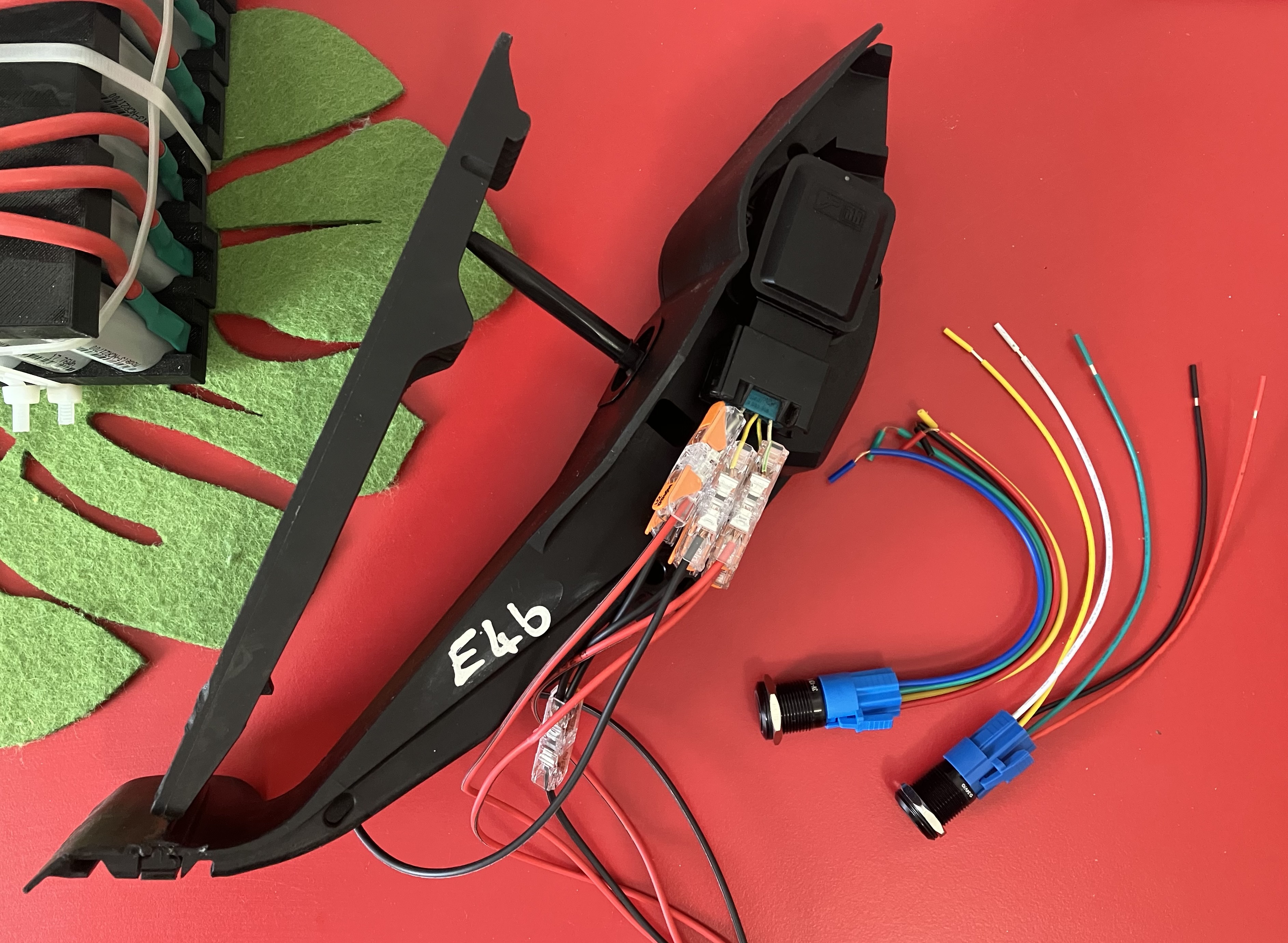
Engine control systems which use a physical cable to manipulate a throttle are called drive-by-cable, and systems which use wires to communicate with an electronic throttle are called drive-by-wire systems. Most modern vehicles are drive by wire, so you can simply go and get a throttle from your local junk yard and wire it up. I chose to get a BMW E46 throttle pedal, because it was well documented on the openinverter wiki and it had a shape which is amenable to bolting to the floor of my kombi.
I made sure to buy one that had the wire stubs connected to it so that I didn’t have to go looking for proprietary connectors. Here is the pinout, as screenshotted from the openinverter wiki.
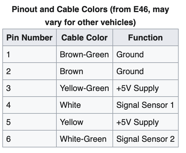
Luckily the wire colours all matched up, so it was a simple job of connecting each wire to the corresponding wire of the ZombieVerter (pins 31-24 of the diagram above). The two ground wires were joined together, as were the two +5V supply lines.
You’ll notice that there are actually two thottle signals. This is quite common in drive-by-wire systems, and is for added redundancy. As you might imagine, this is a pretty critical signal line, so having two signals that must agree with each other is a pretty important safety feature. That said, the ZombieVerter will work just fine if you only use one.
Where we are now
This is the current state of our rat’s nest of wires. Don’t worry, I’ll make up a proper harness with new wires and proper crimps when I actually install this in a car! What we have achieved today is circled in green.
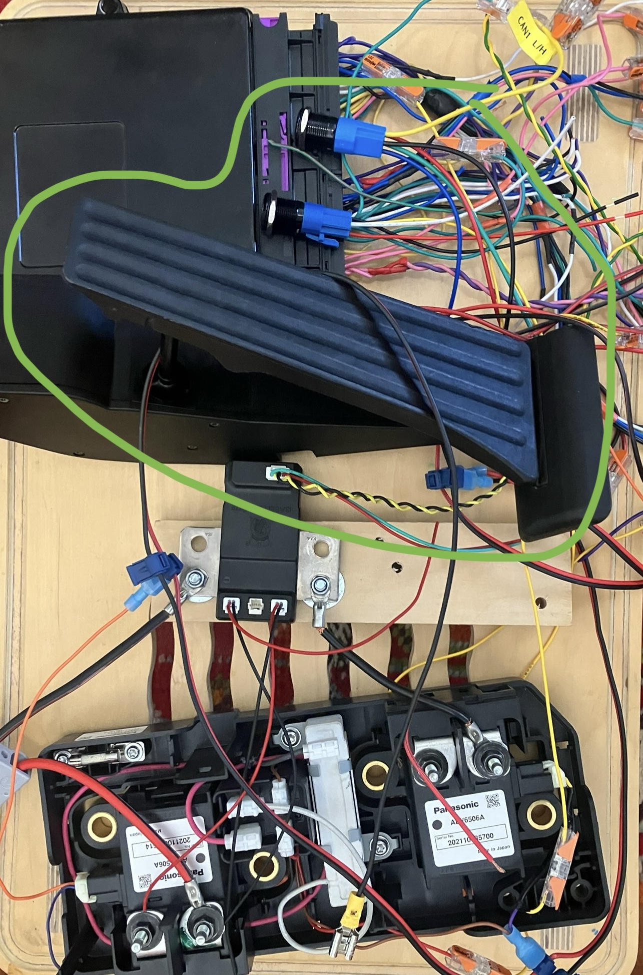
Now that this is all wired up to a permanet 12V energy source (AKA ‘your car battery’), I press a lathing button for ignition, press another momentary button to bring up the HV circuit, and then press the pedal to send throttle signals to the VCU. I can see the throttle values changing in the ZombieVerter web interface, so all is working well. It looks like we have a control system in need of something to drive!