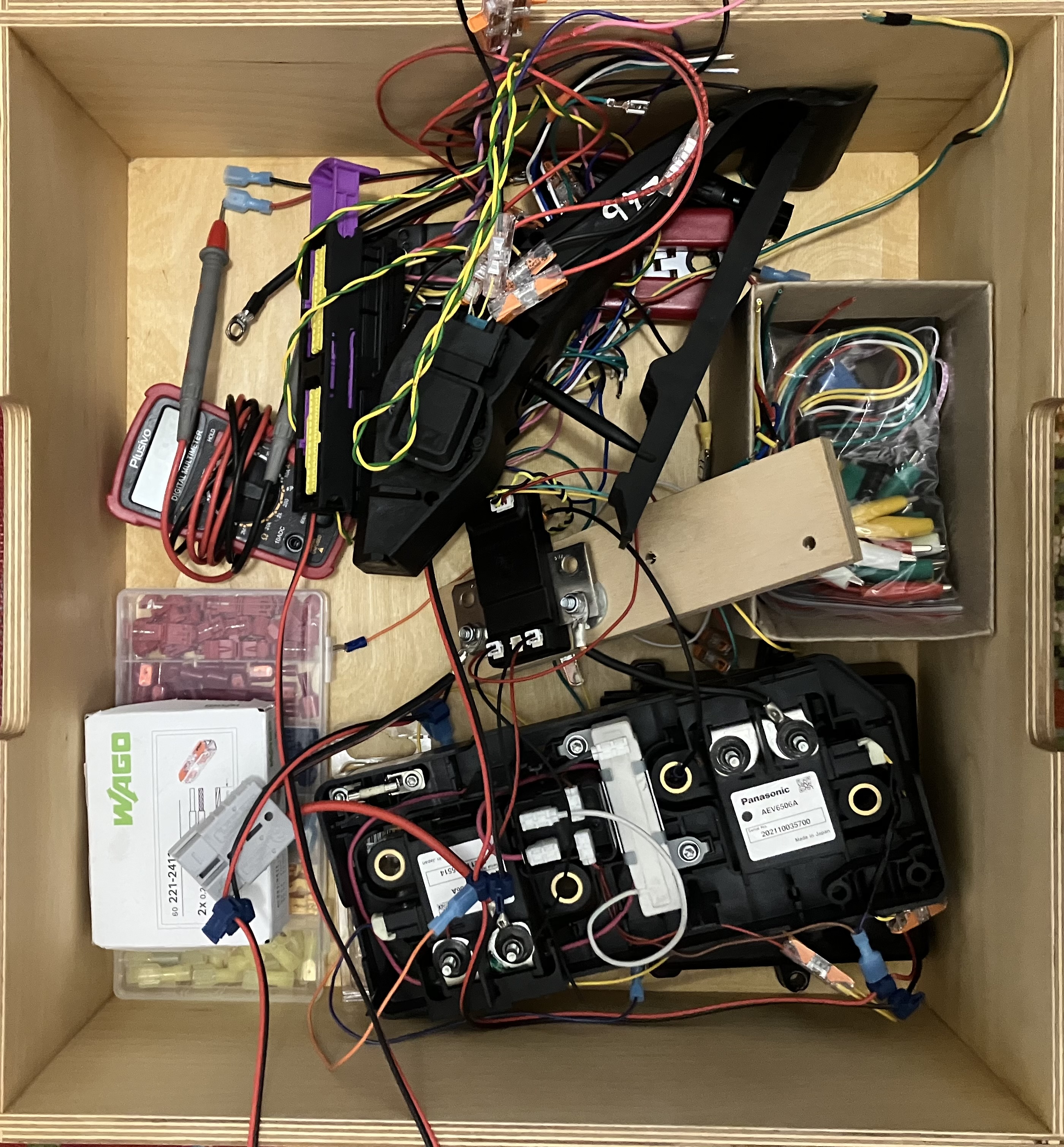
DIY EV 6: Tangent on car control circuits
What we have done thus far
At this point, we have fulfilled all the conditions required to turn on our EV high voltage circuit.
We have connected up the precharge circuit and automated the operation of that circuit via our vehicle control unit (VCU). Practically speaking, what this means is that when we turn our ignition on (by turning our car key), our VCU receives a signal and connects the high voltage battery to the EV components via low current circuit. It then watches the voltage on the EV component side until it equalises with the battery voltage, and then it connects the battery to the EV components via a high current circuit and closes the low current circuit.
So now our components are all ’live’ and supplied with the energy required to turn the motor. However, none of the computer brains required to operate any of this stuff is poered up or networked.

The low voltage circuits
This blog post is all about the low voltage circuits. We are at the point where the high voltage energy is getting to where it needs to go. Now, we need to control the EV components. As with all aspects of EV conversion, this is achieved by means of electrical circuits.
We actually need to wire up two kinds of circuits. The first type of circuit is the low voltage power circuit. All of these ‘components’ are actually controlled by computers inside them. And those computers need to be powered up. When you connect everything up with high voltage, these computers are not powered up. They generally run on either 12v or 5v. So we need to provide them with power lines. The tricky thing here is connecting the power lines in such a way that they all turn on at the appropriate time, that they turn off at the appropriate time, and they are supplied with adequate power to operate in a wide range of conditions.
The second type of circuit is for signalling. All electrical devices need some sort of user input to operate. A microwave has buttons that a human pushes. Those buttons have some sort of wiring behind them that goes to a little computer that then sets the microwave to run for a certain time.
A little bit of history
Old cars (say, pre 2004), often relied on signal wires or physical cables to operate. For instance, when you pressed down on the accelerator pedal, it actually was attached to a cable (like a bicycle brake cable) that ran all the way to your motor, where it was attached to a mechanism that physically opened or closed a valve to allow air and fuel into your motor. My kombi works like this. If the cable snaps, you need to get someone to sit on top of the engine and physically pull the cable to rev the engine.
Modern vehicles generally replace physical signals with electrical ones. There was a transition period of about 20 years where the physical stuff was replaced with electrical lines that signalled by means of voltage. In this method of control, a wire would vary from 0-5V depending on the level of depression of the accelerator pedal), and that voltage was read on the other side as an indication of how much to open the throttle with a little servo motor.
This resulted in cars with a huge mess of wires, and, as cars got older and wiring degraded, all sorts of weird stuff started happening. Like, ‘when it is damp my car doesn’t accelerate smoothly’, which could mean an engine problem, or it could just mean that your wiring is a bit dodgy and the 5v signal is intermittent when the humidity is high.
But, eventually, most car manufacturers converged on a proper network protocol called CANBUS. With CAN, there are just two wires. These are like telephone wires, and digital signals are sent along them. ALL the components are connected to the same two wires (or little offshoots), and all devices broadcast and listen on the wires. So the pedal can broadcast, “I am a pedal, and I am pressed 30%”. All components receive this message, and most ignore it. But the throttole will hear that message and go, “ooh, that means give 30% open throttle” and acts accordingly.
Back to our regular programming
In unmodified form, the Syncro has a combination of physical control systems and electrical signalling. Most of that stuff will remain unmodified - I am focusing on just replacing the means of locomotion - the engine and associated systems. We will use a little bit of everything in our conversion.
We are already using CANBUS in our little test setup. The ZombieVerter speaks to the IVT Shunt via CANBUS. And, the ZombieVerter uses signal wiring to open and close the contactors. Our accelerator pedal will transmit its level of depression via a varying 5V signal to the VCU. Our VCU will then calculate a torque request which is will transmit to the inverter via CANBUS.