DIY EV 5: Precharge Automation
So a couple of posts ago I implemented a manual precharge circuit.
Strictly speaking, you could perform the following steps manually, but we want to automate it.
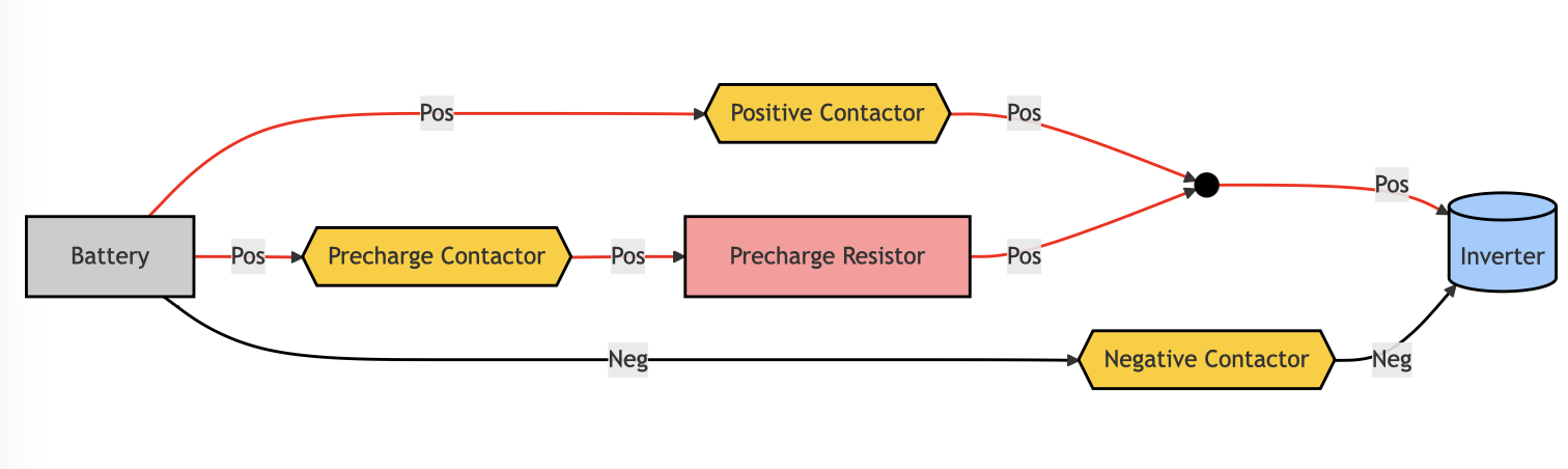
- Turn on the negative contactor. Now the negative terminal is live, but the positive is dead so the circuit is still broken.
- Turn on the precharge contactor. Now the positive terminal is live, and the circuit is complete, but the voltage comes up slowly.
- Wait until the voltage on the inverter side of the curcuit is the same as the voltage on the battery side.
- When the voltages are the same, turn on the positive contactor. Now full current can flow.
- Turn off the precharge contactor.
In order to automate these steps, we need some controller that can monitor voltages on the battery side and inverter side of the high voltage circuit and turn on the contactors in the right sequence. I am making use of the Zombieverter for this purpose. The Zombieverter is an all in one EV controller (and it’s open source), so I’ll use it to control all sorts of other things as well.
Zombie and IVT-S Shunt
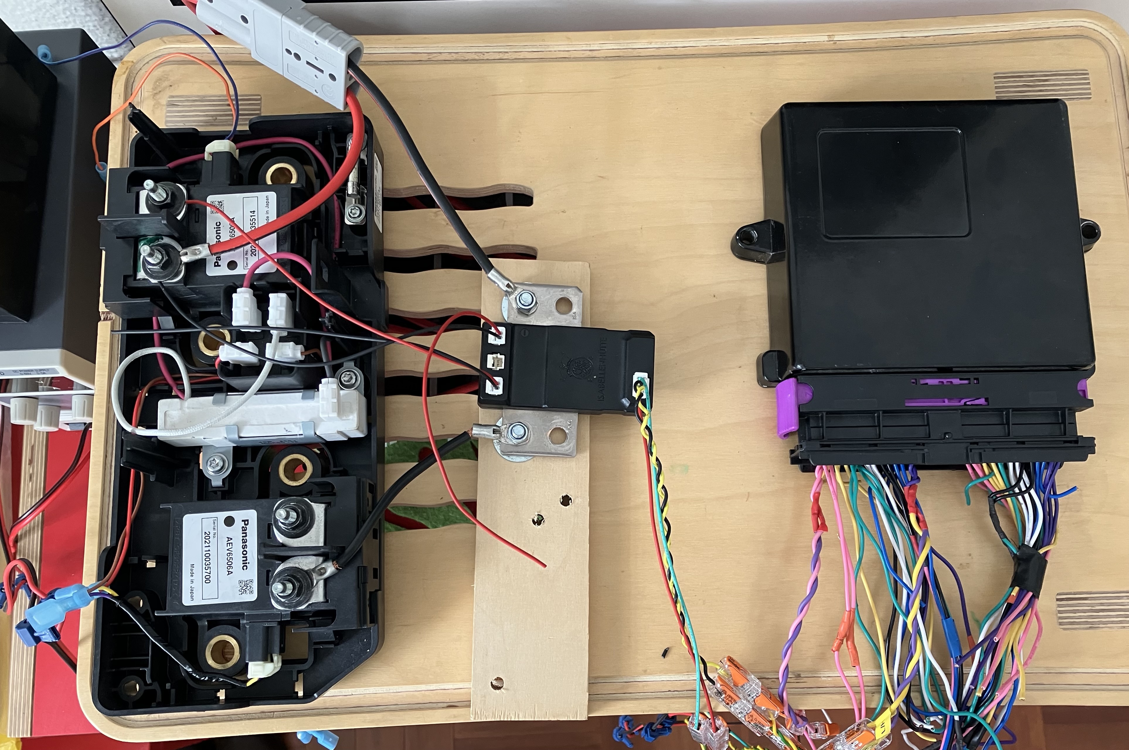
The Zombieverter works with a voltage measuring device called an IVT Shunt.
You place the shunt in between the battery and negative contactor, and then you connect its positive wires (there are 3) to various places along your high voltage circuit. The shunt, when operating correctly, will send data about the voltage and current passing through each of those locations via CANBUS.
The Zombieverter listens to those CAN messages to find out what the voltages are at various locations along the circuit and opens and closes contactors accordingly.
Simple enough in theory, but quite tricky to do if you haven’t done it before. Firstly, you need to know that CAN networks need a terminating resistor at each end. The Zombie has one, and you need to check if your shunt has one or not - some models do and some don’t. Then you need to power up your Zombie, connect to the wifi interface, visit the embedded website, and follow unstructions here to intialise the shunt.
Once it’s initalised, you should see stable voltages in the parameter reference on the web page.
At this point you are able to monitor, but not control. Next up you need to connect all the negative 12v leads of the contactors to a common ground rail, and then connect each contactor to the corresponding pin of the Zombieverter pinout. The pinout can be found on at the openinverter link abot, but I’ve included it here for reference.

I have Zombie powered via pins 55 ad 56, the IVT Shunt connected via CAN circuit going into pins 43 and 44, and contactor 12V lines connected to 33, 35 and 36. THis allows me to control the contactors via the web interface.
Next up, I’ll wire up the ignition and start lines so that I can flip a switch and have the contactors automatically close.