DIY EV 2: Power Supplies, Test Batteries and Precharge Circuits
I have been advised to hook up all my components on a bench before I rip anything out of my bus. This is because only a small proportion of EV projects succeed, and if you disable your car as step 1, you end up with a much bigger mess to clean up when you give up.
Getting power
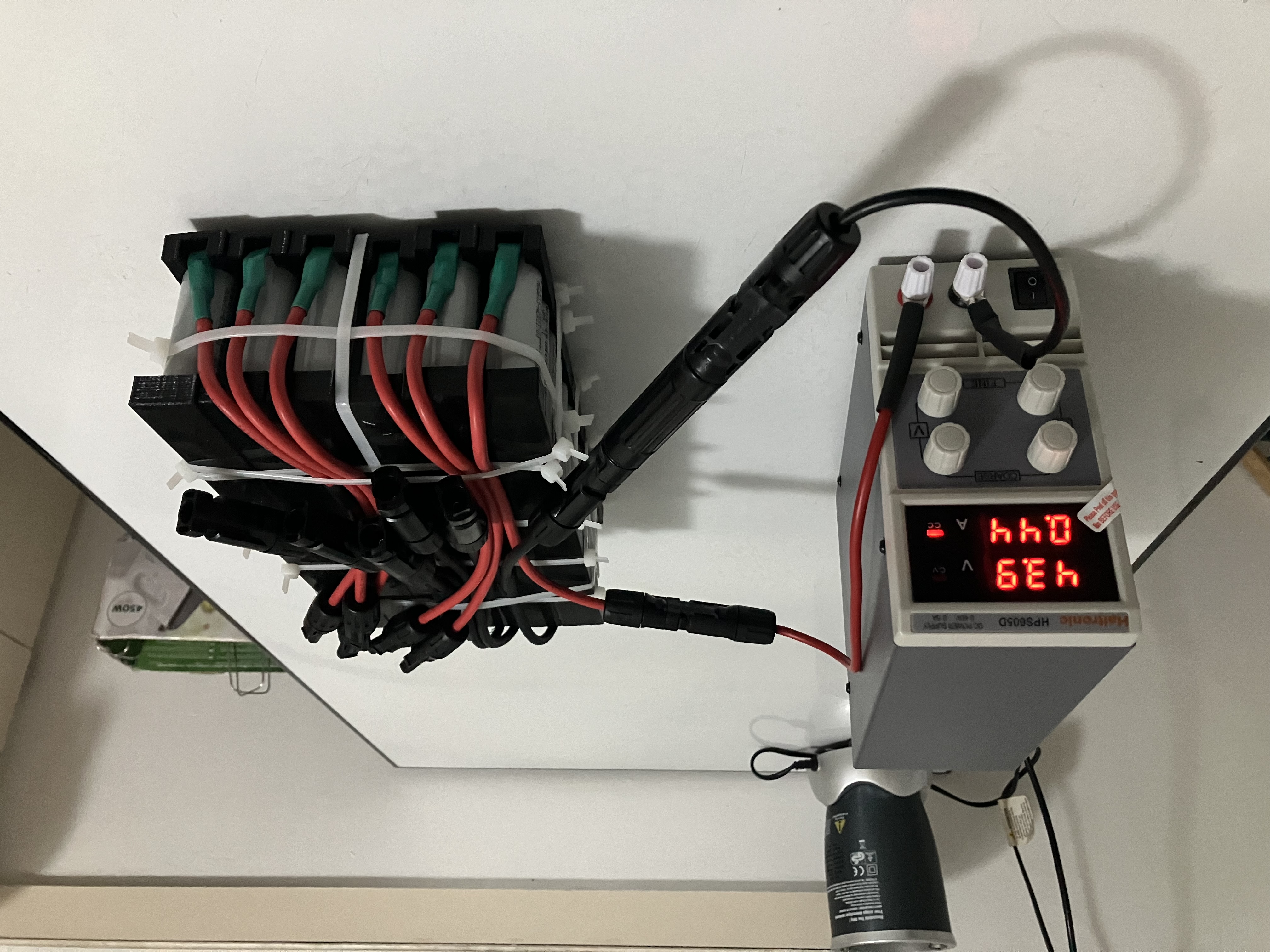
It was good advice. I immediately discovered that I could’t even hook everything up yet, because I don’t have a power source! So I decided to buy a 0-60V bench power supply. This enables me to precisely set the voltage I want to supply to low voltage components. This supply isn’t actually able to run any of my high voltage components, because most of the Outlander stuff only powers on at 200V, but it’s enough to start building out circuits.
In order to actually operate the high voltagr stuff, I had to figure out how to get 200V+ of DC power into my garage for as little money as possible. In the end, I found someone who would assemble 7 x 12S 21700 Lithium Ion cell strings, which I can then connect in series. The idea is that each of the packs then come to 44.4V nominal - a low enough voltage to handle safely, and quite versatile - but when wired in series I get 310V. It’s small and light (about the size and weight of a 6 pack), but can supply about 6kw continuous.
I don’t think I’ll worry about a BMS for now, I’ll just measure the voltage from time to time and top up from bench power.
Powering something on the high voltage circuit
The next problem is, how do I charge it? Well, I scratched my head about for a while before the folks at openinverter pointed out that I have a perfectly good high voltage DC charger - the EV charger I bought! So I’ll just make that step 1 of my ‘bench assembly’ exercise: get the charger working and hooked up to the battery pack so that when I switch on the wall mains, the test pack is charged up to a target voltage and then turned off. Once I get that working, I’ll move on to connecting the high voltage components to the battery.
Turns out that was a bad idea. I spend several months trying to get my EV charger working, but it’s really hard without a BMS because it’s CANBUS operated. So it really can only come later. I’ll stick with manually topping up each string from bench power.
Powering something on the high voltage circuit v2
Ok, well, EV high voltage systems are actually pretty simple, especially if you ingore the complexity of how to charge it. You have a battery, and you have an inverter. That’s pretty much it. BUT THERE IS A CATCH.
When you connect up a whole lot of fancy electronics (i.e an inverter) to a massive power source (i.e a battery), the onrush of current into the inverter can damage the circuitry. This is because the inverter is going from a ‘resting voltage’ of 0V to 300V instantly, which is quite violent. So, you need to bring up the voltage slowly. Welcome to PRECHARGE CIRCUITS!
What is a precharge circuit?
Basically, you need to spoon feed the downstream components a slow ramp up of voltage until the voltage on the battery size is roughly equal to the voltage on the component side. Then you can open up a full connection to allow really high currents to flow though. How do you clow down current? With a resistor. So that’s exactly what we do.
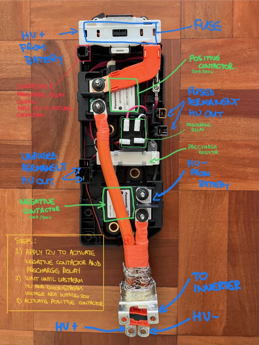
Typically you would place all the contactors inside the battery box so that the terminals coming out of the battery box are dead unless the prechage circuit is activated.
Here’s a handy term translator for the diagram below.
- Battery -> Energy source
- Contactor -> A fancy switch
- Resistor -> A thing that slows down current
- Inverter -> An energy sink
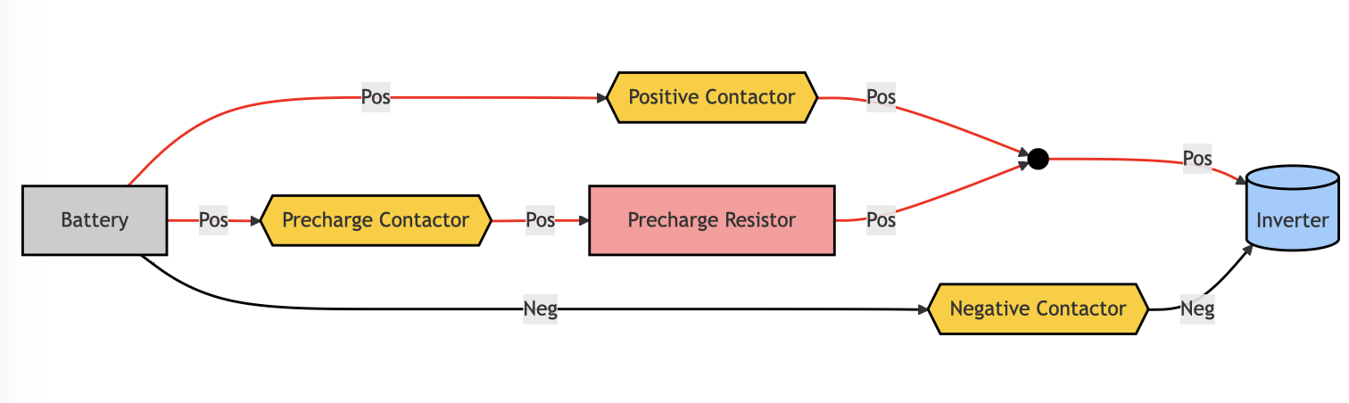
Basically, ’turning on’ an EV involves the following steps:
- Starting out, all contactors are open. There is no dangerous electricity outside of the battery box.
- Turn on the negative contactor. Now the negative terminal is live, but the positive is dead so the circuit is still broken.
- Turn on the precharge contactor. Now the positive terminal is live, and the circuit is complete, but the voltage comes up slowly.
- Wait until the voltage on the inverter side of the curcuit is the same as the voltage on the battery side.
- When the voltages are the same, turn on the positive contactor. Now full current can flow.
- Turn off the precharge contactor.
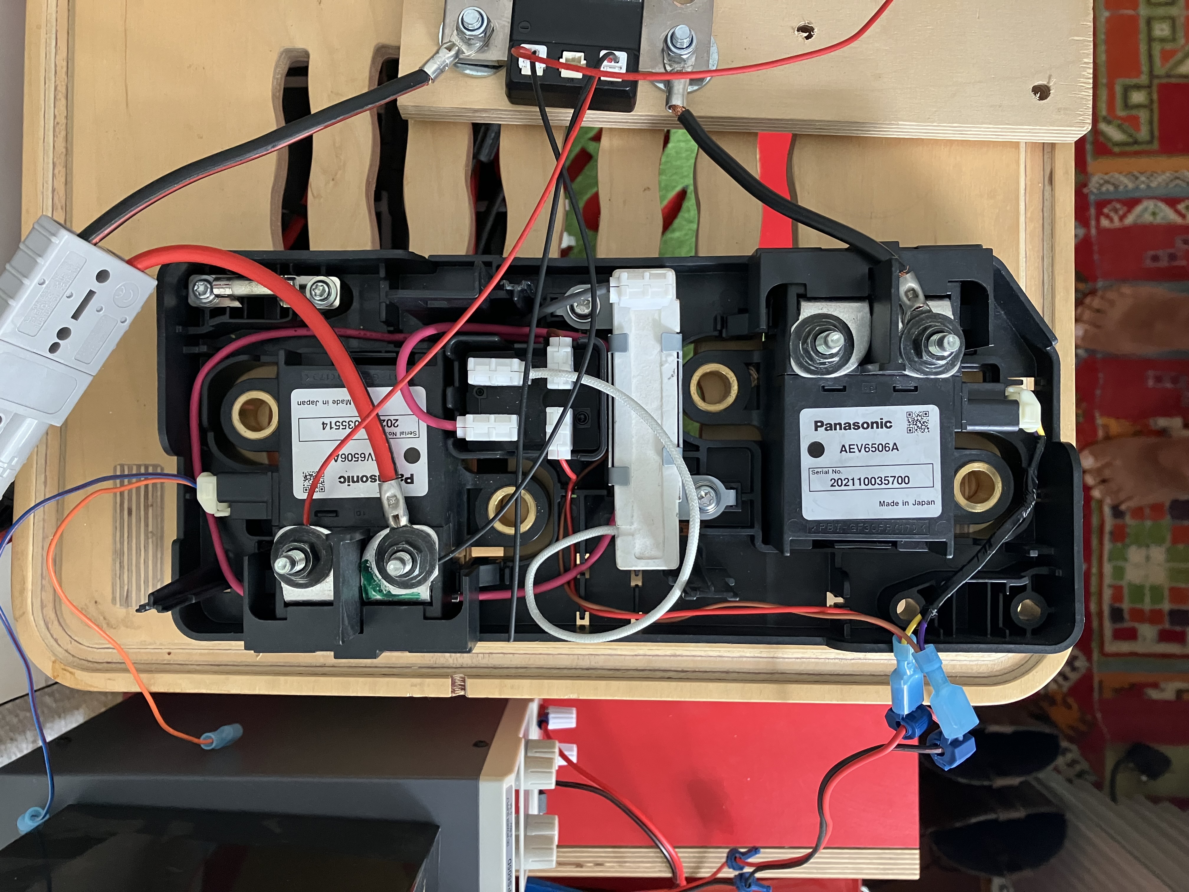
All of the contactors are activated by giving them 12V. They are deactivated by removing 12V. So, here is a photo of a precharge circuit manually set up in my office. It’s a bit difficult to see, but the circuit is exactlt he same as the diagram above. I operate it by manually connecting the contactor inputs to a 12V source.
Here is an annotated version of the above circuit, which is out of a Nissan Leaf, labeling each of the parts. I also posted this picture on the openinverter wiki.